

MACHOIRES FREIN M38&M38A1 (JEU DE 4)

Post war Jeep CJ3B Brakes
Post war Jeep CJ5 Brakes
Post war Jeep M38A1 Brakes
Brake Service Standards - CJ-3B
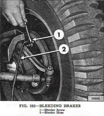
Bleeding Brakes
The hydraulic brake system must be bled whenever a fluid line has been disconnected or air gets into the system. A leak in the system may sometimes be indicated by the presence of a spongy brake pedal. Air trapped in the system is compressible and does not permit the pressure, applied to the brake pedal, to be transmitted solidly through to the brakes. The system must be absolutely free from air at all times. When bleeding brakes, bleed at that wheel with the longest line from the master cylinder first, the next longest second, etc. During the bleeding operation the master cylinder must be kept at least 3/4 full of hydraulic brake fluid. To bleed the brakes, first carefully clean all dirt from around the master cylinder filler plug. Remove the filler plug and fill the master cylinder to the lower edge of filler neck. Clean off all bleeder connections at all four wheel cylinders. Attach bleeder hose and fixture to right rear wheel cylinder bleeder screw and place end of tube in a glass jar, and submerged in brake fluid. Open the bleeder valve one-half to three-quarters of a turn. See Fig. 283.
Depress the foot pedal, allowing it to return very slowly. Continue this pumping action to force the fluid through the line and out of the bleeder hose which carries with it any air in the system. When bubbles cease to appear at the end of the bleeder hose, close the bleeder valve and remove the hose. After the bleeding operation at each wheel cylinder has been completed, fill the master cylinder reservoir and replace the filler plug. Do not re-use the liquid which has been removed from the lines through the bleeding process because of air bubbles and dirt. (P4, p225-226)
Brake Pedal Adjustment - Varies from Vehicle to Vehicle from 3/4" to 1.5" of Travel
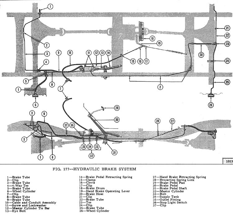
There should always be at least 1/2" [12.7 mm.] free pedal travel before the push rod engages the master cylinder piston. This adjustment is accomplished by shortening or lengthening of the brake master cylinder eye bolt Fig. 277. This is done so the primary cup will clear the by-pass port when the piston is in the off position, otherwise the compensating action of the master cylinder for expansion and contraction of the fluid in the system, due to temperature changes, will be destroyed and cause the brakes to drag. Note: Some older 'Jeep' vehicles may develop side movement of the clutch and brake pedals resulting from wear of the pedals, shafts, and bushings. One way to compensate for this wear is to install a pedal slack adjuster kit, Part No. 921936. (P-5, p226)
Brake Adjustment
The locations of the brake adjusting eccentrics are shown in Fig. 284 and 286. First be certain that the brake pedal has 1/2" [12.7 mm.] free travel. Jack up the wheels to clear the floor. Adjustment is made by rotating the brake shoe eccentric, Fig. 286. With a wrench loosen the lock nut for the forward brake shoe, hold the lock nut and with brake wrench W-213 turn the eccentric towards the front of the vehicle until the brake shoes strikes the drum, then while turning the wheel with one hand release eccentric until the wheel turns freely. Hold the eccentric in position and fasten the lock nut. To adjust the reverse shoe, repeat this operation only turn the eccentric towards the back of the vehicle. Do this on all four brakes.
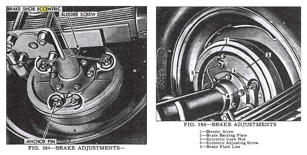
Check the fluid level in the master cylinder. If additional adjustment is required or when relining the brakes, reset the anchor pins as follows: With the shoe and lining assemblies installed and the brake drum in place loosen the anchor pin lock nuts at the bottom of the backing plate. Adjustment is made by turning the eccentric anchor pins toward each other, Fig. 284, and down until the shoes are set to the proper clearance as determined by feeler gauges. The recommended shoe setting is .005" [.127 mm.] clearance at the heel (lower end), and .008" (.203 mm.] at the toe (upper end) of the brake shoe lining. On early models, a slot was provided in the brake drum for checking these clearances. This slot was eliminated in later models. (P-6, p226)
Looking for Brake parts for your vintage Willys or Jeep? Search Brakes by Category or by Diagram
* Excerpt from the Service Manual for Universal Jeep Vehicles pages 225-226
Cette pièce est destinée à la restauration de véhicules militaires historiques. L'ajustement, l'alignement, l'ébavurage ou la retouche font partie de ce travail et sont inhérents à la nature de ces marchandises. Des différences de cotes existent également entre véhicules d'origine.
Le montage exige une connaissance technique du véhicule. Vous hésitez sur la compatibilité avec votre version ? Écrivez-nous avant l'achat à info@willys.be.
ALL_CATEGORIES : GROUPE 12 - FREINS - M38A1
Cette pièce convient à :
| Modèle | Années |
|---|---|
| Jeeps militaires | |
| Willys M38A1 | 1952, 1953, 1954, 1955, 1956, 1957, 1958, 1959, 1960, 1961, 1962, 1963, 1964, 1965, 1966, 1967, 1968, 1969, 1970, 1971 |
| Série CJ | |
| Jeep CJ-3B | 1953, 1954, 1955, 1956, 1957, 1958, 1959, 1960, 1961, 1962, 1963, 1964, 1965, 1966, 1967, 1968 |
| Jeep CJ-5 | 1955, 1956, 1957, 1958, 1959, 1960, 1961, 1962, 1963, 1964, 1965, 1966, 1967, 1968, 1969, 1970, 1971, 1972, 1973, 1974, 1975, 1976, 1977, 1978, 1979, 1980, 1981, 1982, 1983 |
📐 Schémas & dessins techniques
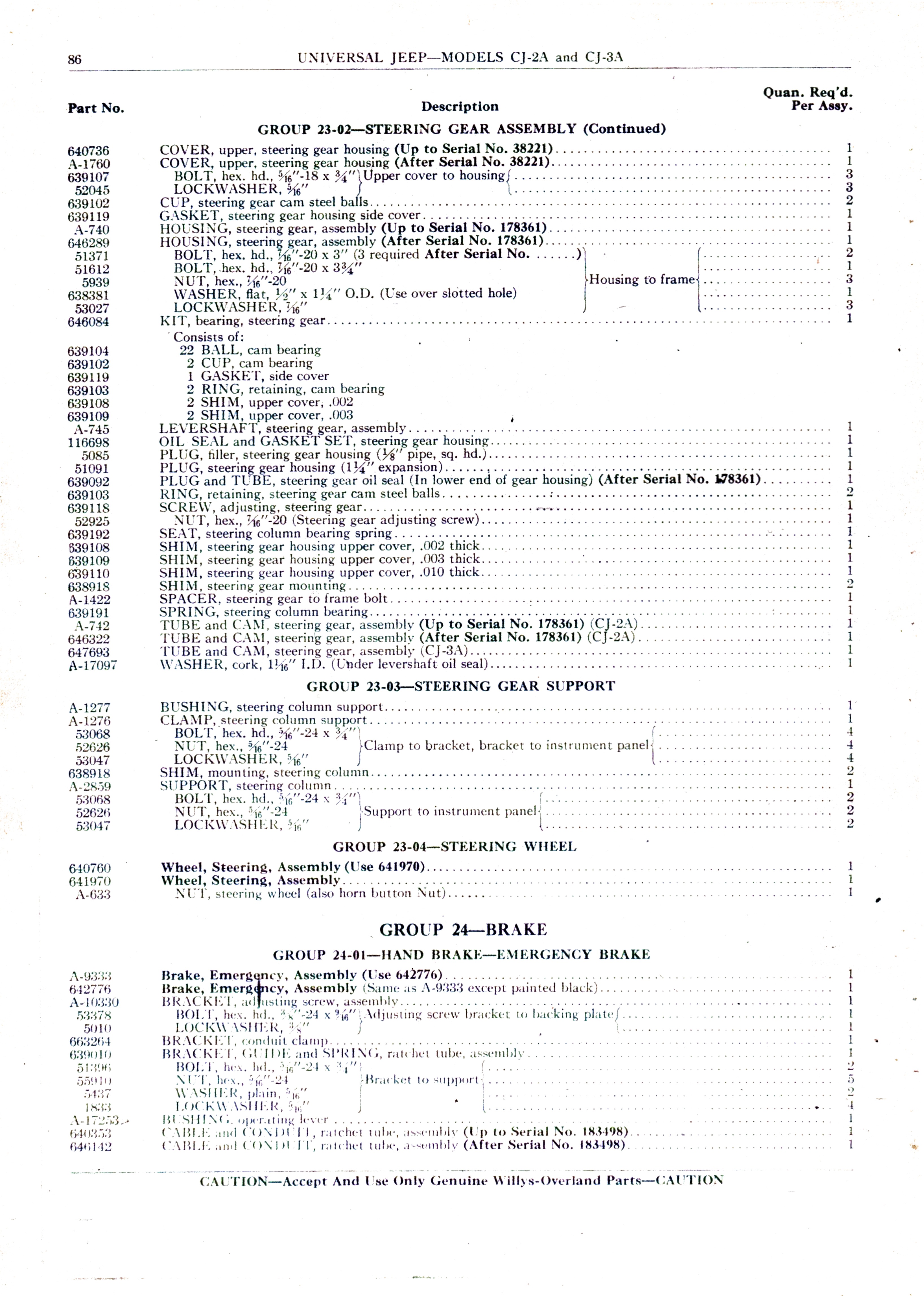
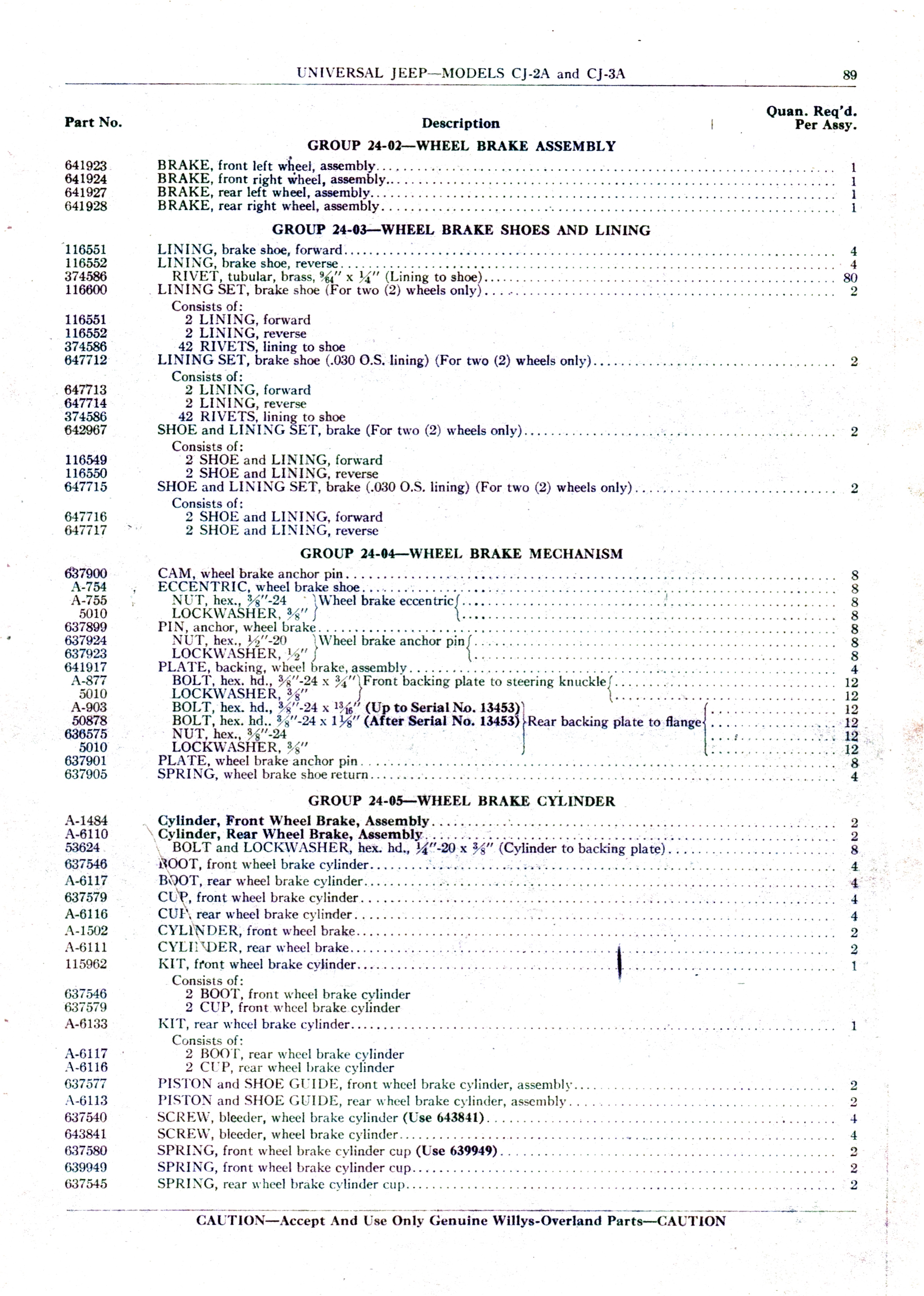
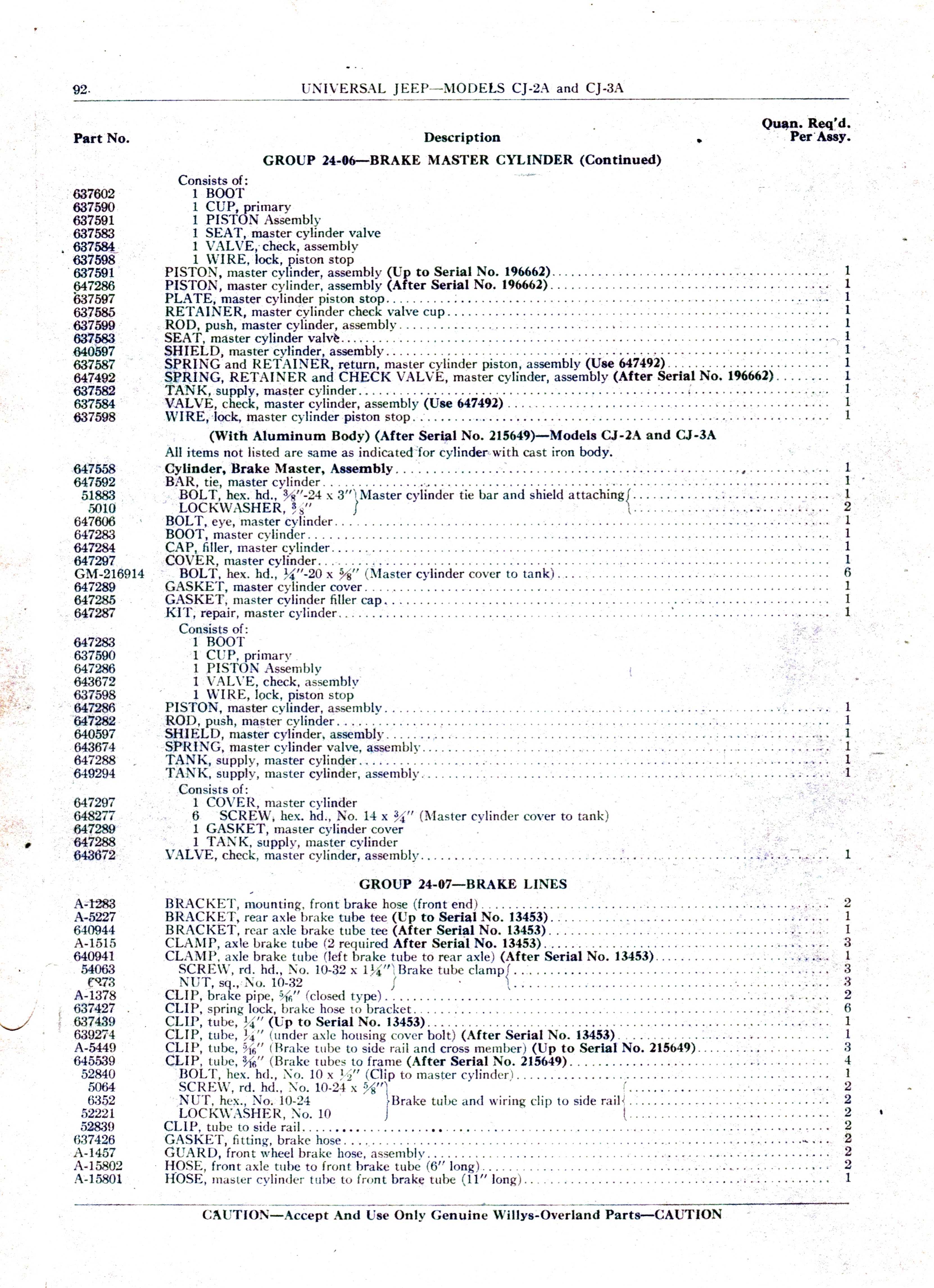
Extrait du Technical Manual original CJ2A_PL_1949 — Parts List — uniquement pour Willys CJ-2A / CJ-3A (1949)